路徑
The <path> element is the most powerful element in the SVG library of basic shapes. It can be used to create lines, curves, arcs, and more.
Paths create complex shapes by combining multiple straight lines or curved lines. Complex shapes composed only of straight lines can be created as <polyline> elements. While <polyline> and <path> elements can create similar-looking shapes, <polyline> elements require a lot of small straight lines to simulate curves and don't scale well to larger sizes.
A good understanding of paths is important when drawing SVGs. While creating complex paths using an XML editor or text editor is not recommended, understanding how they work will allow to identify and repair display issues in SVGs.
The shape of a <path> element is defined by one parameter: d. (See more in basic shapes.) The d attribute contains a series of commands and parameters used by those commands.
Each of the commands is instantiated (for example, creating a class, naming and locating it) by a specific letter. For instance, let's move to the x and y coordinates (10, 10). The "Move to" command is called with the letter M. When the parser runs into this letter, it knows it needs to move to a point. So, to move to (10, 10) the command to use would be M 10 10. After that, the parser begins reading for the next command.
All of the commands also come in two variants. An uppercase letter specifies absolute coordinates on the page, and a lowercase letter specifies relative coordinates (e.g., move 10px up and 7px to the left from the last point).
Coordinates in the d parameter are always unitless and hence in the user coordinate system. Later, we will learn how paths can be transformed to suit other needs.
直線命令
There are five line commands for <path> nodes. The first command is the "Move To" or M, which was described above. It takes two parameters, a coordinate (x) and coordinate (y) to move to. If the cursor was already somewhere on the page, no line is drawn to connect the two positions. The "Move To" command appears at the beginning of paths to specify where the drawing should start. For example
M x y
(or)
m dx dy
In the following example there's only a point at (10, 10). Note, though, that it wouldn't show up if a path was just drawn normally. For example

<svg width="200" height="200" xmlns="http://www.w3.org/2000/svg">

  <path d="M10 10"/>

  <!-- Points -->
  <circle cx="10" cy="10" r="2" fill="red"/>

</svg>
There are three commands that draw lines. The most generic is the "Line To" command, called with L. L takes two parameters—x and y coordinates—and draws a line from the current position to a new position.
L x y
(or)
l dx dy
There are two abbreviated forms for drawing horizontal and vertical lines. H draws a horizontal line, and V draws a vertical line. Both commands only take one parameter since they only move in one direction.
H x
(or)
h dx

V y
(or)
v dy
An easy place to start is by drawing a shape. We will start with a rectangle (the same type that could be more easily made with a <rect> element). It's composed of horizontal and vertical lines only.

<svg width="100" height="100" xmlns="http://www.w3.org/2000/svg">

  <path d="M 10 10 H 90 V 90 H 10 L 10 10"/>

  <!-- Points -->
  <circle cx="10" cy="10" r="2" fill="red"/>
  <circle cx="90" cy="90" r="2" fill="red"/>
  <circle cx="90" cy="10" r="2" fill="red"/>
  <circle cx="10" cy="90" r="2" fill="red"/>

</svg>
We can shorten the above path declaration a little bit by using the "Close Path" command, called with Z. This command draws a straight line from the current position back to the first point of the path. It is often placed at the end of a path node, although not always. There is no difference between the uppercase and lowercase command.
Z
(or)
z
So our path above could be shortened to
<path d="M 10 10 H 90 V 90 H 10 Z" fill="transparent" stroke="black"/>
The relative forms of these commands can also be used to draw the same picture. Relative commands are called by using lowercase letters, and rather than moving the cursor to an exact coordinate, they move it relative to its last position. For instance, since our rectangle is 80×80, the <path> element could have been written as
<path d="M 10 10 h 80 v 80 h -80 Z" fill="transparent" stroke="black"/>
The path will move to point (10, 10) and then move horizontally 80 points to the right, then 80 points down, then 80 points to the left, and then back to the start.
In these examples, it would probably be simpler to use the <polygon> or <polyline> elements. However, paths are used so often in drawing SVG that developers may be more comfortable using them instead. There is no real performance penalty or bonus for using one or the other.
曲線命令
There are three different commands that can be used to create smooth curves. Two of those curves are Bézier curves, and the third is an "arc" or part of a circle. You might have already gained practical experience with Bézier curves using path tools in Inkscape, Illustrator or Photoshop. There are an infinite number of Bézier curves, but only two simple ones are available in <path> elements: a cubic one, called with C, and a quadratic one, called with Q.
貝塞爾曲線
三次貝塞爾曲線 C 稍微複雜一些。三次貝塞爾曲線每個點需要兩個控制點。因此,要建立三次貝塞爾曲線,需要指定三組座標。
C x1 y1, x2 y2, x y
(or)
c dx1 dy1, dx2 dy2, dx dy
這裡最後一組座標(x,y)指定了線條的結束位置。另外兩組是控制點。(x1,y1)是曲線起點處的控制點,(x2,y2)是曲線終點處的控制點。控制點本質上描述了從每個點開始的線條的斜率。貝塞爾函式然後建立一個平滑的曲線,從線條開始處的斜率過渡到線條結束處的斜率。
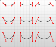
<svg width="190" height="160" xmlns="http://www.w3.org/2000/svg">

  <path d="M 10 10 C 20 20, 40 20, 50 10" stroke="black" fill="transparent"/>
  <path d="M 70 10 C 70 20, 110 20, 110 10" stroke="black" fill="transparent"/>
  <path d="M 130 10 C 120 20, 180 20, 170 10" stroke="black" fill="transparent"/>
  <path d="M 10 60 C 20 80, 40 80, 50 60" stroke="black" fill="transparent"/>
  <path d="M 70 60 C 70 80, 110 80, 110 60" stroke="black" fill="transparent"/>
  <path d="M 130 60 C 120 80, 180 80, 170 60" stroke="black" fill="transparent"/>
  <path d="M 10 110 C 20 140, 40 140, 50 110" stroke="black" fill="transparent"/>
  <path d="M 70 110 C 70 140, 110 140, 110 110" stroke="black" fill="transparent"/>
  <path d="M 130 110 C 120 140, 180 140, 170 110" stroke="black" fill="transparent"/>

</svg>
上面的例子建立了九條三次貝塞爾曲線。當曲線向右移動時,控制點水平方向上逐漸展開。當曲線向下移動時,它們與端點的距離越來越遠。需要注意的是,曲線從第一個控制點方向開始,然後彎曲以便它沿著第二個控制點方向到達。
可以將多個貝塞爾曲線串聯起來,建立擴充套件的平滑形狀。通常情況下,點一邊的控制點將是另一邊使用的控制點的映象,以保持斜率恆定。在這種情況下,可以使用三次貝塞爾曲線的簡寫版本,由命令 S(或 s)指定。
S x2 y2, x y
(or)
s dx2 dy2, dx dy
S 生成與之前相同的曲線型別 - 但如果它在另一個 S 命令或 C 命令之後,則假設第一個控制點是之前使用的控制點的映象。如果 S 命令不在另一個 S 或 C 命令之後,則將游標的當前位置用作第一個控制點。結果與使用相同引數的 Q 命令生成的曲線不同,但相似。
下面展示了這種語法的一個例子,在左側的圖中,指定的控制點以紅色顯示,推斷的控制點以藍色顯示。
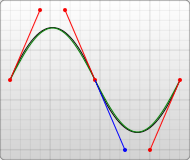
<svg width="190" height="160" xmlns="http://www.w3.org/2000/svg">
  <path d="M 10 80 C 40 10, 65 10, 95 80 S 150 150, 180 80" stroke="black" fill="transparent"/>
</svg>
另一種型別的貝塞爾曲線,即使用 Q 呼叫的二次曲線,實際上比三次曲線更簡單。它需要一個控制點,該控制點確定曲線在起點和終點處的斜率。它需要兩個引數:控制點和曲線的終點。
注意:q 的座標增量都是相對於前一點的(也就是說,dx 和 dy 不是相對於 dx1 和 dy1 的)。
Q x1 y1, x y
(or)
q dx1 dy1, dx dy
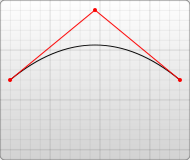
<svg width="190" height="160" xmlns="http://www.w3.org/2000/svg">
  <path d="M 10 80 Q 95 10 180 80" stroke="black" fill="transparent"/>
</svg>
與三次貝塞爾曲線一樣,有一個簡寫方式可以將多個二次貝塞爾曲線串聯起來,使用 T 呼叫。
T x y
(or)
t dx dy
此簡寫方式檢視之前使用的控制點,並從該控制點推斷出一個新的控制點。這意味著在第一個控制點之後,只需指定端點即可建立相當複雜的形狀。
這隻有在之前的命令是 Q 或 T 命令時才有效。如果不是,則假設控制點與前一點相同,並且只會繪製直線。
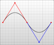
<svg width="190" height="160" xmlns="http://www.w3.org/2000/svg">
  <path d="M 10 80 Q 52.5 10, 95 80 T 180 80" stroke="black" fill="transparent"/>
</svg>
兩種曲線都產生相似的結果,儘管三次曲線允許對曲線的具體形狀有更大的自由度。決定使用哪種曲線取決於情況,並取決於線條的對稱程度。
圓弧
使用 SVG 可以建立的另一種型別的曲線是圓弧,使用 A 命令呼叫。圓弧是圓或橢圓的一部分。
對於給定的 x 半徑和 y 半徑,有兩個橢圓可以連線任意兩點(只要它們在圓的半徑內)。沿著這兩個圓中的任何一個,都可以採取兩種可能的路徑來連線這些點 - 所以在任何情況下,都有四種可能的圓弧可用。
因此,圓弧需要相當多的引數。
A rx ry x-axis-rotation large-arc-flag sweep-flag x y
a rx ry x-axis-rotation large-arc-flag sweep-flag dx dy
在開始時,圓弧元素接受 x 半徑和 y 半徑的兩個引數。如果需要,請參閱 <ellipse> 的行為方式。最後兩個引數指定結束描邊的 x 和 y 座標。這四個值一起定義了圓弧的基本結構。
第三個引數描述了圓弧的旋轉。這最好用一個例子來解釋。
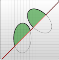
<svg width="320" height="320" xmlns="http://www.w3.org/2000/svg">
  <path d="M 10 315
           L 110 215
           A 30 50 0 0 1 162.55 162.45
           L 172.55 152.45
           A 30 50 -45 0 1 215.1 109.9
           L 315 10" stroke="black" fill="green" stroke-width="2" fill-opacity="0.5"/>
</svg>
此示例顯示了一個 <path> 元素,它以對角線方式穿過頁面。在它的中心,切出了兩個橢圓圓弧(x 半徑 = 30,y 半徑 = 50)。在第一個圓弧中,x 軸旋轉保持為 0,因此圓弧圍繞的橢圓(以灰色顯示)垂直向上和向下定向。然而,對於第二個圓弧,x 軸旋轉設定為 -45 度。這將橢圓旋轉,使其沿路徑方向使其短軸對齊,如示例影像中的第二個橢圓所示。
對於上面的未旋轉橢圓,只有兩個不同的圓弧,而不是四個可供選擇,因為從圓弧的起點和終點繪製的線穿過橢圓的中心。在一個稍微修改的示例中,可以看出形成四個不同圓弧的兩個橢圓。
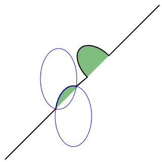
<svg xmlns="http://www.w3.org/2000/svg" width="320" height="320">
  <path d="M 10 315
           L 110 215
           A 36 60 0 0 1 150.71 170.29
           L 172.55 152.45
           A 30 50 -45 0 1 215.1 109.9
           L 315 10" stroke="black" fill="green" stroke-width="2" fill-opacity="0.5"/>
  <circle cx="150.71" cy="170.29" r="2" fill="red"/>
  <circle cx="110" cy="215" r="2" fill="red"/>
  <ellipse cx="144.931" cy="229.512" rx="36" ry="60" fill="transparent" stroke="blue"/>
  <ellipse cx="115.779" cy="155.778" rx="36" ry="60" fill="transparent" stroke="blue"/>
</svg>
注意,每個藍色橢圓都是由兩個圓弧形成的,取決於順時針或逆時針移動。每個橢圓都有一個短圓弧和一個長圓弧。這兩個橢圓只是彼此的映象。它們沿著從起點到終點的線翻轉。
如果起點和終點的距離超過了橢圓的 x 和 y 半徑所能到達的距離,則橢圓的半徑將被最小程度地擴充套件,以便它可以到達起點和終點。此頁面底部的互動式 codepen 很好地演示了這一點。為了確定橢圓的半徑是否足夠大以至於需要擴充套件,需要求解方程組,例如 Wolfram Alpha 上的這個方程組。此計算適用於起點和終點為 (110,215)→(150.71,170.29) 的未旋轉橢圓。解 (x,y) 是橢圓的中心。如果橢圓的半徑太小,則解將是 虛數。第二個計算適用於起點和終點為 (110,215)→(162.55,162.45) 的未旋轉橢圓。解有一個小的虛數部分,因為橢圓只是略微擴充套件了。
上面提到的四種不同的路徑由接下來的兩個引數標誌決定。如前所述,路徑仍然可以圍繞兩個可能的橢圓進行,並且在兩個橢圓上都有兩個不同的可能路徑,因此有四種可能的路徑。第一個引數是 large-arc-flag。它決定圓弧是否大於或小於 180 度;最終,此標誌決定圓弧將圍繞給定圓圈向哪個方向移動。第二個引數是 sweep-flag。它決定圓弧是從正角度還是負角度開始移動,這本質上選擇將圍繞哪個圓圈進行移動。下面的示例顯示了所有四種可能的組合,以及每種情況下的兩個圓圈。
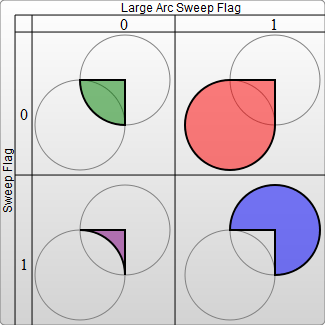
<svg width="325" height="325" xmlns="http://www.w3.org/2000/svg">
  <path d="M 80 80
           A 45 45, 0, 0, 0, 125 125
           L 125 80 Z" fill="green"/>
  <path d="M 230 80
           A 45 45, 0, 1, 0, 275 125
           L 275 80 Z" fill="red"/>
  <path d="M 80 230
           A 45 45, 0, 0, 1, 125 275
           L 125 230 Z" fill="purple"/>
  <path d="M 230 230
           A 45 45, 0, 1, 1, 275 275
           L 275 230 Z" fill="blue"/>
</svg>
圓弧是一種在繪圖中建立圓或橢圓片段的簡單方法。例如,餅圖需要為每個片段使用不同的圓弧。
如果從 <canvas> 過渡到 SVG,圓弧可能是最難學習的東西,但也是功能最強大的。完整的圓和橢圓是 SVG 圓弧難以繪製的唯一形狀。因為繞圓的任何路徑的起點和終點都是同一點,所以可以選擇無限多個圓,而實際路徑是未定義的。可以透過使路徑的起點和終點略微傾斜,然後用另一個路徑段連線它們來近似這些形狀。例如,可以使用每個半圓的圓弧來繪製一個圓。在這一點上,使用真正的 <circle> 或 <ellipse> 節點通常更容易。此互動式演示可能有助於理解 SVG 圓弧背後的概念:https://codepen.io/lingtalfi/pen/yaLWJG(僅在 Chrome 和 Firefox 中測試過,可能無法在你的瀏覽器中執行)。